Tech Tips
GFS Installation Instructions
Please take the time to read these instructions before you begin the installation of the GFS. Proper care must be taken when installing the GFS for the system to work as design and tested by Speed Concepts.
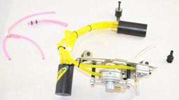
The first step of the installation of the GFS will require you to remove one clutch cover bolt and one water pump cover bolt. Note the order of the washers, lock washers, lock nuts, and rubber grommets before you start to remove parts as they were shipped from SwedeTech. The small tubing at the end of the studs is only used to keep hardware in place while shipping.
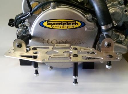
Start with the left side (towards rear of engine) of the flat mounting plate. Remove the stud from the rubber grommet with your fingers and install through the clutch cover, using only your fingers to install. Next, install the ½” long spacer, followed by the lock washer, and then the nut. Tighten the lock nut to 7 ft/lbs or 84 in/lbs. Install regular washer and then rubber grommet. Lightly tighten grommet with fingers until snug.
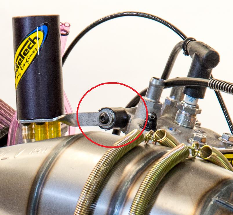
Move to the right side (towards the front of engine) of the flat mounting plate. Remove the stud from the rubber grommet with your fingers and install through the water pump cover, using only your fingers to install. Next, install the two lock washers, and then the nut. Tighten the nut to 7 ft/lbs or 84 in/lbs. Install the regular washer and then the rubber grommet. Lightly tighten grommet with fingers until snug. Align angled mounting brackets with rubber grommets and install the spring washer and button head Allen bolts and tighten to 7 ft/lbs or 84 in/lbs. Double check the hardware you installed.
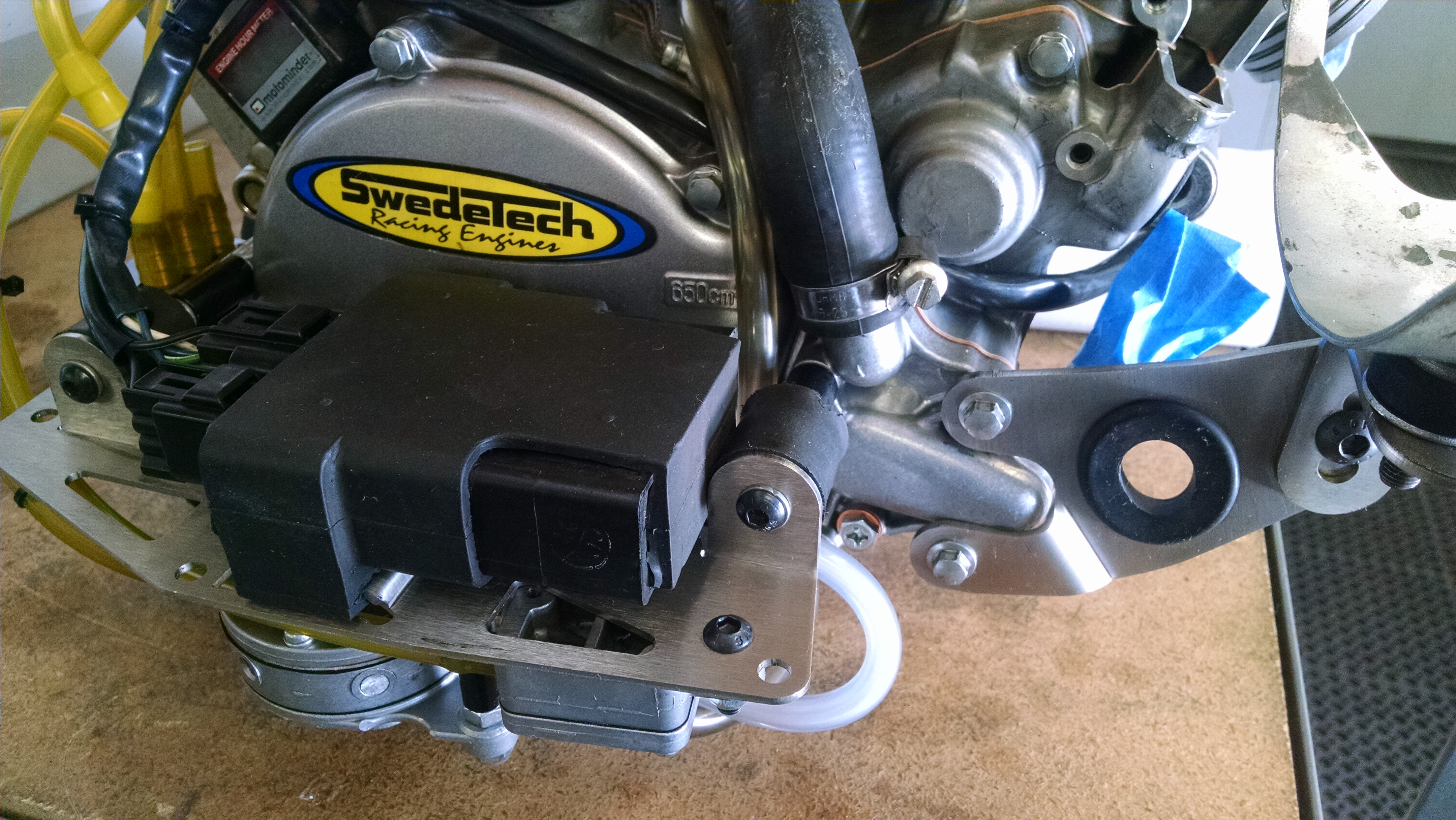
The next step is to mount the upper reservoir to the OEM engine mount boss that is located on the head. Remove the countersunk bolt from the rubber grommet. Place the bolt thru the head boss, then secure to rubber grommet. Before you secure the button head Allen, make sure the top of the reservoir is parallel with the chassis frame rails. Once this is in the proper position, tighten the button head. Double check hardware and move to next step.
Before connecting the carburetor to the GFS, measure the go karts fuel tank supply, return, and vent nipples for a minimum ID of 3/16”. This is very important for proper operation. You will also have to install a second vent line. Either in the Fuel tank or the gas cap. Do not connect the two vent lines together. They must be vented separately. If you are using a vent catch can, make sure all nipples are drilled to a minimum of 3/16”. The catch tank must have at least two air vents with an ID of ¼”.
The next step is to connect the GFS to the carburetor. You must use a stock carburetor for the GFS to work properly. This system will not work on a carburetor that was previously converted to a pump around style system. This system will also not work if an aftermarket needle or needle seat have been installed in the carburetor. These instructions are for the PWM carburetor. If you are using the PWK carburetor, please refer to the supplemental instructions. Starting with the upper reservoir, there is one line that is open, coming off the rear nipple. This line goes to the carburetor inlet nipple. The next step is to hook up the vent lines and float bowl overflow. Remove the two 5” vent lines that are equal length and zip tied as a pair. Keep these vent lines zip tied together. The GFS comes with the proper vent lines pre-cut to the proper length. The first three lines are directly connected to a plastic manifold. The line that is 1.5” in length will hook to the nipple on the bottom of the float bowl. This is the overflow for the float bowl. The next line you will connect will measure 4.25”. Looking from the back of the engine, this line connects to the right side cast carburetor vent that is perpendicular to the carburetor body. The line measuring 8” will connect to the left side cast carburetor vent nipple that is also perpendicular to the carburetor body. Now with the two remaining equal length 5” vent lines, connect one to each side of the carburetor vent nipples that are pointing upwards.
From the lower reservoir, you will notice one line that goes into a plastic Y. One line connect to the Y is open. This is a vent line, do not plug or try to connect, this must remain open.
The next step is to connect your pulse line. The pulse line included in the kit is long enough to reach a pulse line fitting installed in the reed cage area on the ignition side of the engine. If the pulse fitting is on the right side(clutch side) of the cases, cut the pulse line to length (approximately 7 ½ - 8”). The final step is to connect your fuel lines that come from the karts fuel tank. You will need to use .25” fuel line and always run a low restriction inline fuel filter in the supply line.
Double check the supply line from karts gas tank and connect to the rectangle fuel pump. The rectangle fuel pump is the pump that supplies the fuel to the system. Check and make sure that the return fuel line to the karts gas tank is the proper line. The return fuel pump is the round fuel pump. DO NOT SWAP THESE PUMPS OR LINES.
Now that your system is connected, double check that all lines are connected securely with hose clamps or safety wire. Make sure the lines are not crimped, smashed, or folded shut. Make sure you are using a fuel filter. Make sure all hardware is tightened properly. One of the most important steps of the installation procedures is to make sure the lines that run from the upper reservoir to the lower reservoir are routed in a manner that does not allow fuel to sit or accumulate in a trapped manner. It is normal for fuel to accumulate in the vent lines draining into the lower reservoir, as long as the fuel level is not above the plastic manifold or the bottom of the float bowl.
Maintenance tips -
- Always have an extra of each fuel pump rebuild kit in your spare parts track box.
- Always remove pulse line hose from fuel pumps after each day of running. This will help keep pumps operating correctly.
- Always make sure your fuel system is vented properly.
- Always make sure the fuel is flowing through the fuel lines, first to the upper reservoir, then to the carburetor. If you do not see fuel flowing from the upper reservoir to the carburetor, do not start the engine. Double check your plumbing and fuel lines to the fuel pumps.
You can order the GFS - Gravity Feed System directly from Swedetech - shopswedetech.com/home.php
For other frequently asked questions, visit our FAQ section - swedetechracing.com/faq/